
Engineered for Reliability
Industries & Applications
Technology & Resource Hub
Optics Wizards & AI-powered Tools
M12 Lenses & other Products
Try this ->: Access Sunex lens database directly from your own AI app
Based in the U.S. and serving customers worldwide for 25 years, Sunex has shipped over 100M lenses and imaging solutions for mission-critical systems with unmatched reliability.
M12 lens Optics Wizards: Comprehensive design and analysis tools and calculators for imaging optics/cameras
M12 lens marketplace: Complete catalog of M12 lenses, buy samples online, download PDF specifications and STP files.
Comprehensive M12 lens literature: Technical calculators, In-depth authoritative whitepapers and the expert guide/insight: what, how and why.
The ultimate M12 lens selection guide
Once the imager is chosen, the process for selecting an M12 lens (also called S mount lens) does not differ from that of selecting other CMOS lenses and consists of the following steps:
Determine the desired field of view (in angles if the object is at infinity, and in actual sizes if the object is at a finite distance).
Calculate the required focal length of the lens, and the image circle size. We have created a wizard to perform this calculation.
Choose an appropriate lens f/# based on similar lighting environment and depth of field requirement. We have created a wizard to calculate the depth of field.
Determine the appropriate lens performance requirements such as modulation transfer function (MTF), chromatic aberration, distortion, and relative illumination.
Specify the mechanical size constraint and reliability requirements.
Imager format and resolution
The starting point is the format size which is linked to the effective area of the imager. The format size definition comes from pre-electronic imaging era. It does not directly represent the diagonal size of the effective area. Commonly seen imager formats and their actual physical sizes are listed below. The imager resolution is the number of effective pixels in the horizontal and vertical directions. The total number of pixels is often used to represent the nominal resolution of an imager.
Good articleon sensor size trade-offs
Lens image circle vs. imager size
Effective focal length and field of view
Once lens image circle is determined, the next step is to determine the appropriate lens focal length (EFL) required to achieve the desired field of view. The lens EFL is an intrinsic property of the lens independent of the imager used. The max. lens field of view (FOV) is specified for the image circle size. However, the field of view of CCD/CMOS camera depends on both the lens EFL and the size of the imager area. If the lens distortion is small (known as rectilinear lenses), the following formula can be used to calculated the camera FOV:
Nyquist frequency and image quality
Relative illumination and telecentricity
where ychief is the image height for an off-axis chief ray, and yrefis a reference image height for the off-axis field angle. For normal field of view lenses, the reference image height isdefined as:
where f is the effective focal length and θ is the field angle. The resulting distortion is known as “rectilinear” or “f-tan” distortion. Most standard photographic lenses have low rectilinear distortion. For wide-angle and fisheye lenses, the reference image height is typically chosen as the product of focal length and field angle (in radians):
The resulting distortion is known as “f-theta” distortion. Please note that a zero f-theta distortion lens can still look very “distorted” visually. It is possible to “tailor” distortion in such a way that the off-axis resolution is enhanced from the standard “f-theta” type. Sunex has developed unique designs and manufacturing know-how to provide wide-angle lenses with tailoreddistortion. We also provide Photoshop-compatible plug-in to “de-warp” images taken with tailored distortion lenses.
Visual impact of various lens distortion (value is calculated for thecorners)
Flare, scattering and ghost images
Optical low-pass filter (OLPF)
An OLPF is made of 1 to 3 layers of optical birefringent materials such as quartz. Each birefringent layer splits a light ray by polarization as shown below:
Pick the right m12 lens or s-mount lens for your project
Talking to our clients, we noticed that selecting the right M12 lens (also called S mount lens) for a specific project or simply limiting the options to a range of applicable lenses is not trivial.
Sunex’s Optical wizards are free online tools (registration required) designed to assist you in selecting the proper M12 lens or any other CMOS lens for your applications.
If wizards, tools, and configurators are not your cup of coffee (or even if they are), we are always here to talk to you in person! Contact Sunex
There are different approaches when it comes to selecting the right lens, depending on whether you already selected a specific imager or have hard requirements for FOV and EFL. No matter your starting point, Sunex’s Optical wizards will help you in the selection process:
Search imager database: We have built a database of popular CMOS imagers from major suppliers. You can search for an imager based on the manufacturer’s name, PN and imager resolution. Once an imager is identified, you can then go on to search for a list of compatible lenses.
Find a lens by imager specification: Given the imager resolution and pixel pitch, this tool will compute a list of imager key characteristics, and search our database for all matching lenses.
Field of view and EFL calculator: This tool will calculate the required lens effective focal length to achieve a desired field of view in degree or vice versa. This tool will work for all lenses including wide-angle and fisheye lenses with a significant amount of distortion.
Depth of field calculator: This tool will calculate the depth of field and hyper-focal distance for a given lens focal length and f/# . It requires the user to enter the maximum blur size in µm. It works for both infinite and finite conjugate systems.
Imaging optics solver: For a given object and image size requirement, this tool calculates the required focal length of the lens based on first-order optics. It then recommends a suitable lens structure and focal length based on the object field size. It is a good starting point for solving finite conjugate problems.
Search lens by optical parameters: This is a collection of advanced search tools.
M12, S-Mount, C-Mount, CS-Mount…What does it all mean?
M12, S-Mount, C-Mount…What does it all mean?
If you’ve been searching for a small-camera lens, you’ve likely encountered terms like M12, S-Mount, Board-Mount, Miniature Lens, C-Mount, CS-Mount, and more. With so many names floating around, it’s easy to get confused. So, why does it seem like there are so many options? And how do you know which one is right for your project? In an effort to answer these questions, we thought we’d explore what these terms mean, where they come from, and how they relate to your lens selection.
In the beginning (at least in this story), there was C-mount.
Going back decades, the standard for interchangeable industrial lenses (as opposed to most consumer photographic cameras) was the C-mount. The C-Mount lens, still a staple in industrial machine vision, some security camera circles, and university labs, was one of the first solutions to standardize the lens mount format. It paved the way even before the days of CCD and early CMOS cameras.
The thread of a C-Mount is 1-32; more specifically it’s 1” in diameter with 32 TPI (threads per inch), or: M25.4 x 0.794mm. The C-mount has a standardized back focal length (BFL) of 0.69” (17.526mm), meaning that all these lenses were designed with the same flange BFL. In practice, the lens was screwed all the way down to the mount until tight and then a focusing mechanism allowed fine focus depending on the object distance. This of course made for some long TTL lenses, especially those with a long EFL. To help address the length issue, the CS-Mount lens format was introduced. While it uses the same thread and mounting strategy as a C-mount, it has a shorter fixed BFL of 0.4931” (12.526mm).
Although the C/CS-Mount makes for very straight-forward interchangeability, there are several drawbacks to their formats.
First, the standardization of the FBFL is somewhat arbitrary in terms of optimizing optical performance and actually imposes a design constraint. Second, since the FBFL is fixed, the lens must have a secondary focus mechanism, and since the standard 32 TPI thread is not fine enough to focus 10s of microns of DOF (depth of focus), the lens must incorporate a relatively complex mechanical means of achieving fine focus. Third, the fixed FBFL alone means the TTL of the lens will be at least 12.5mm long (more for C-Mount) before even considering the physical length of the lens. Fourth, the C/CS mount is typically (but not always) integrated into the housing or chassis of the camera with the sensor-board mounted separately. This means there is no direct mechanical reference or interface between lens and sensor, which you’ll know could be a potential source of error from our AA article (Sunex Knowledge Center: What Is Active Alignment?). Lastly, but admittedly not exclusive to C/CS lenses, there is a tendency to add more features since they are interchangeable. While these features may be ideal in applications where flexibility is needed, it is less desirable for fixed, high-volume circumstances. Often, these features also come at the cost of well, cost, in addition to reliability, design and performance tradeoffs.
Despite these drawbacks and the fact that C/CS-Mounts aren’t technically Board-Mounts, they still have plenty of utility. It’s important to recognize how these formats helped establish standards for lens mounting and continue to serve many applications today.
“Board-Mount” or “S-Mount” lenses address the C/CS-Mount issues in a few ways. Board-mount lenses have no dependency on a fixed FBFL/BFL and no need for a separate focus mechanism. They are designed to thread into a threaded mount directly attached to the sensor PCB. The thread doubles as the focusing mechanism because it typically has a 0.5mm or 0.35mm pitch making it fine enough to focus a lens (see our article Sunex Knowledge Center: Basic Thread Considerations). It also eliminates many (but not all) sources of alignment error between lens and sensor by placing the lens directly on the sensor board. Of course, this means that the BFL, FBFL and MBFL are coupled to the focal position of the lens. This means the focal position changes slightly from camera to camera, but the differences are on the order of 10’s of microns, so it is generally not a problem.
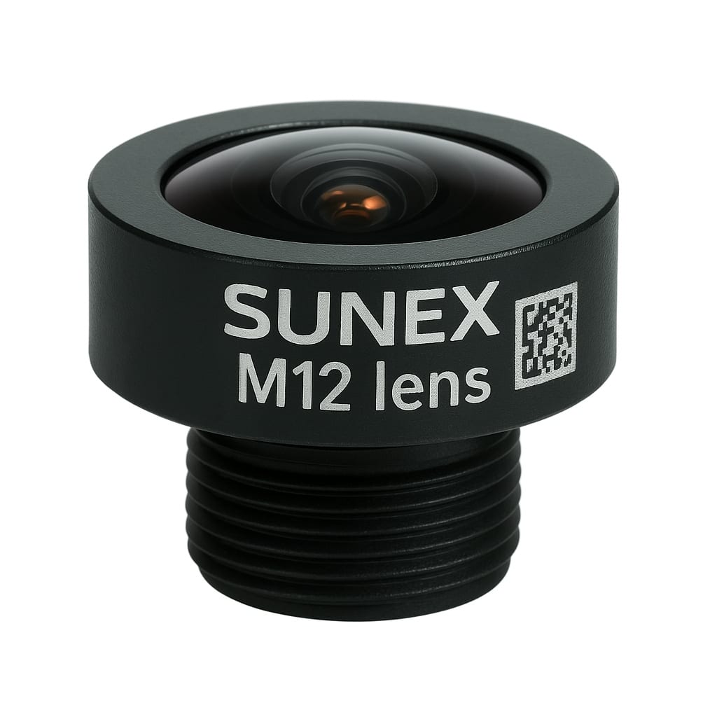
A natural result of this board-mount approach is the proliferation of optimized, design-for-purpose lenses. “Board-Mount” is simply a general, all-encompassing term for lenses that are mounted and focused in this way. Within this broad category, M12 lenses, also referred to as S-mount, are the most common. Both terms refer to an M12x0.5mm lens, that is, a 12mm diameter lens with 0.5mm thread pitch.
In fact, “M12” has become almost synonymous with Board-Mount but in truth, while all M12’s are Board Mounts, not all Board-Mount lenses are M12 lenses. Other popular sizes of board-mount lens include M14, M10, M8, M7 and even smaller. Thread pitch tends to scale roughly with diameter and M8x0.35mm are fairly common, but in theory any size thread can be used with any diameter lens. For example, M12 “fine-focus” (M12x0.35) or even larger diameters may be specified in critical higher-megapixel applications, to gain a bit more focus control.
M12 and other Board-Mount lenses are also ideally suited to active alignment because there is not a fixed BFL and therefore no secondary focus requirement. In Active Alignment, an M12 lens can have its thread removed and can be focused and fixed directly over the sensor in one step without impacting the rest of the design. For example, you could prototype with a threaded M12 lens and mount and then go straight to mass-production with a threadless version of the same lens and mount.
The other C/CS-Mount issues are addressed by M12 and other Board-Mount lenses as well. Since FBFL is not fixed, the lens design can converge on the best performance, independent of BFL. This generally leads to a much shorter overall solution. It also eliminates the need for complex focusing mechanism internal to the lens. And since such lenses tend to be built-to-purpose, gone is the need for costly and complex varifocal, aperture and locking mechanics. There are also typically commensurate gains in performance, consistency and reliability for M12 lenses compared to their C/CS counterparts because there are fewer trade-offs. While Sunex does offer C/CS lenses, we have also pioneered large-format Board-Mount lenses, such as M20x0.5 and larger. These lenses bring the old C/CS standard into the modern age by allowing them to be mounted directly over the sensor with short BFLs, with the possibility of Active Alignment. But in the world of miniature cameras, the M12 “Board-Mount” still reigns supreme, no matter what you call it.
Expert Insight: the right sourcing strategy for M12 lens
Selecting the right lens sourcing strategy has direct, long-term consequences on image performance, supply continuity, and program economics. The market currently offers three distinct channels: internet platforms, catalog-style intermediaries, and direct OEM partnerships. Each offers benefits at different phases of development, but each also carries distinct risks that grow or shrink as projects move from concept to fielded products.
This whitepaper provides a practical framework to evaluate the trade-offs among the three channels. It integrates real-world scenarios across robotics, industrial automation, embedded vision, and drone imaging, and it attempts to quantify lifecycle impacts using a Total Cost of Ownership (TCO) approach to lens sourcing. The conclusion is straightforward: Internet platforms and intermediaries are potentially valuable options for speed and flexibility in early phases, but mission-critical systems and volume production benefit most from an OEM partnership that aligns optical design, quality, and supply with the product roadmap, and fostering these relationships from the very beginning of a project can pay dividends in terms of Total Cost of Ownership.
Figure 1. Comparison of sourcing channels across key success factors.
1. The Landscape of M12 Lens Sourcing
M12 board lenses are the workhorses of compact imaging, enabling a wide range of FOV (field of views) and F/#’s in small packages and integrating with modern CMOS sensors across a diverse range of devices. As sensor performance improves and mechanical envelopes shrink, optics must carry a greater burden for contrast, distortion control, relative illumination, and environmental stability.
Industrial automation → Inspection, defect detection, process optimization
Embedded vision → Compact consumer and enterprise devices
Drone imaging → Aerial mapping, agriculture analytics, surveillance
At the same time, the supply landscape has broadened. Low-cost marketplaces put thousands of lens SKUs within a click. Intermediaries curate selections, maintain regional inventory, and reduce friction for small orders. OEM lens manufacturers design, produce, and support lenses at scale with guarantees on performance, process control, and lifecycle. Understanding where each channel fits means separating what matters in the lab from what matters in the field across years of production.
Marketplaces such as Amazon and Alibaba offer unmatched convenience and breadth. They are ideal for quickly assembling a bench of candidate lenses to sample fields of view, mechanical clearances, and basic image quality. However, listings may draw from anonymous, mixed, or end-of-life lots; coating recipes and glass sets may vary over time; and there is rarely a roadmap commitment or any traceability. For these reasons, internet lenses are effective tools for exploration but are risky foundations for any product that requires repeatability, certification, or long-term serviceability.
Intermediaries and Catalog Resellers
Intermediaries create value by pre-screening suppliers, carrying inventory, and simplifying procurement for small runs. They are particularly helpful between proof-of-concept and pilot, when teams need a consistent part number without committing to an OEM minimum order or a custom design. Yet intermediaries are constrained by their upstream sources. They typically do not control most aspects of the design, including coating, glass sourcing, or process, and they cannot guarantee that a given SKU will remain in production for the lifetime of your product. When volumes increase or performance margins tighten, such constraints can force an unplanned redesign.
OEMs design and manufacture lenses, manage material supply chains, and validate performance against application-specific or even customer-specific requirements. A mature OEM partnership extends beyond the PN; it includes engineering collaboration (field of view and distortion trade-offs, stray light, spectral response), process control (custom parameters, binning, yield management), and lifecycle planning (EOL policies, alternatives, second-source strategy). Although the unit price may be higher at the outset, and lead times require planning, the risk profile and total program cost are significantly lower in mission-critical, multi-year, and high-volume scenarios. For building long-term, win-win relationships where both the customer and the supplier can bring their full strengths to bear, this is the best option.
2. How the Sourcing Channels Fit into the Product Development Cycle
Product development is often a series of changing constraints. Early on, speed dominates: teams need to consider multiple performance envelopes, mounting options, and ISP pipelines. As prototypes evolve into pilots, repeatability and early supply assurances take priority. At design freeze and launch, quality and reliability take precedence, and lifecycle commitments become non-negotiable. To some extent, these shifting constraints map naturally to the strengths of each sourcing channel. The trick is not to get locked into a path that is not scalable to your ultimate goal.
During concept and POC phases, internet platforms can supply breadth and immediacy, if not exactly meeting the spec. Engineers can sample a dozen lenses very quickly to validate basics, such as the field of view, F/#, and first-order mechanical parameters. The goal is to learn quickly, not to lock architecture on a commodity part.
In Pilot and Beta, intermediaries can add value while also having the ability to support small, ongoing projects looking forward. They reduce friction for “sub-MOQ” builds, provide a single catalog with multiple options, and can maintain a buffer stock while customers complete qualification testing. The risk is that the upstream lens may change subtly between lots or disappear altogether (EOL), through no fault of the supplier themselves.
At Design Freeze and Production Ramp, OEMs become essential. The discipline of a controlled design, documented process flow, and optionally active alignment to the sensor removes variability that would otherwise manifest as yield loss, RMAs, or artifacts in the image. In small quantities, this may be tolerable, as you can hand-sort, but in production, it is unacceptable. Reliable OEMs also lock product lifecycles to the customer roadmap, preventing surprise discontinuities during scale-up and mass production, and for aftermarket support. If the customer started out with an “internet lens,” which somehow made it this far in the design cycle, this is where TCO starts to become a major issue for so-called inexpensive lenses. The cost and schedule stress of redesigning and implementing new optics at this stage typically ripples far beyond the lens itself.
Figure 2. Conceptual suitability of each channel across the major development stages.
3. Real-World Industry Examples
A robotics integrator building a bin-picking camera used inexpensive internet-sourced lenses to evaluate several fields of view. The prototypes worked until thermal cycling at the factory floor revealed focus drift and increased distortion at temperature extremes. Transitioning to an OEM design with thermally balanced materials and tighter assembly tolerances stabilized focus and cut field failures by more than half. Redesign was required, but was done early on, and the cost was more than offset by avoiding RMAs and line downtime.
In defect inspection, modulation transfer function (MTF) consistency directly affects false positives. A machine builder using standard catalog lenses encountered lot-to-lot variation that pushed MTF just below the acceptance window for some lots. After consulting an OEM lens manufacturer, the OEM suggested using binned (sorted) elements and specially controlled assembly torque and case-specific OQC testing. Qualification passed on the first attempt, and the program recovered three months of schedule with significant improvement in false positives (yield rate).
A compact enterprise device ramped from 200 to 30,000 units per year. Its catalog lens was discontinued midway through ramp, triggering an unexpected optical redesign and FCC re-test, resulting in sudden costs and delays. A subsequent OEM engagement was able to deliver a mechanically drop-in lens replacement optimized for the same sensor with consistent shading and improved relative illumination, locked to a five-year supply plan.
An agriculture drone platform needed RGB and near-IR imagery while meeting strict mass and vibration constraints. Early experiments with off-the-shelf lenses exposed coating degradation and decenter sensitivity under vibration profiles as a key spec. An OEM solution combined a dual-channel design with IR-optimized coatings, ruggedization and active alignment to the sensor, enabling repeatable NDVI computation and faster regulatory approvals.
4. Total Cost of Ownership (TCO): Why Upfront Price Is Not Total Price
TCO aggregates all costs required to deliver and sustain a product: engineering hours, yield losses, RMAs, replacements, qualification delays, and the risk-weighted cost of supply disruption. Internet platforms often minimize unit price but externalize many of these costs; intermediaries reduce some variability but do not eliminate upstream risk; OEMs reduce lifecycle costs through design control, process discipline, and roadmap alignment.
A simple way to visualize this is to model cumulative lifecycle cost over time. Internet-sourced parts start low but accelerate as failures and redesigns accumulate. Intermediary-sourced parts fare better, but may still increase due to limited control over process drift or EOL. OEM parts often – not always -start at a higher price but remain relatively stable over the product’s lifetime.
Figure 3. Conceptual TCO curves. Internet platforms minimize upfront price but often maximize lifecycle cost; OEM curves are higher initially but flatter over time.
5. Strategic Recommendations and Decision Framework
Start fast, but do not anchor architecture to commodity parts is the key. Use internet platforms to accelerate learning but treat those lenses as disposable tools for discovery. Once the optical envelope is understood, move to controlled sources.
When a pilot demands a few dozen to a few hundred units, intermediaries can be a pragmatic bridge. Validate batches aggressively: check MTF, distortion, shading, and environmental stability across multiple lots. Confirm the reseller’s view of upstream continuity before committing to field trials. Even at low quantities, keep one eye on the future. Could this product ramp to significant volumes? Will your initial choices scale seamlessly? Will this company/product be here to support me in 5 years?
For ramp-up and production, or for those projects which will invariably ramp to high volumes, choose an OEM partnership from the outset that is aligned to your sensor, packaging, and lifecycle plan. Define performance windows and test methods jointly; consider active alignment to stabilize focus and tilt; document change-control and EOL procedures; and synchronize forecasts so material supply and capacity scale with demand.
Finally, incorporate TCO into milestone reviews. A lens that saves a few dollars in the BOM can cost hundreds of thousands of dollars in redesigns and field interventions later. Use TCO models to make these hidden costs visible before they materialize.
Have we validated optical performance across temperature and vibration to production limits?
Is there documented lot traceability and change control for the lens and key materials?
Do we have an agreed roadmap and EOL policy matched to our product lifecycle?
Are yield, binning, and active alignment options defined to protect margins at scale?
Does the supplier offer direct Engineering and QC support?
Have we stress-tested supply continuity with realistic forecast scenarios?
6. Professional Positioning of Intermediaries
Intermediaries should be acknowledged as important participants in the ecosystem. Many provide tangible value: local inventory, simplified procurement, and pragmatic assistance for early deployments. The argument presented here is not that intermediaries lack merit, but that their role is structurally different from a design-and-manufacture partner. This article’s recommendation is therefore not a criticism; it is a risk-managed allocation of roles that aligns channel strengths with project characteristics. When intermediaries source from OEMs, the collaboration can be positive, provided that plan-of-record parts, documentation, and lifecycle commitments remain robust.
Sourcing choices determine more than unit price: they influence image quality, yield, schedule, and customer experience for years to come. Internet platforms and intermediaries accelerate learning and simplify early builds; OEM partnerships stabilize products, reduce lifecycle cost, and protect brand equity in the field. For mission-critical systems in robotics, industrial automation, embedded vision, and drone imaging, the data and experience converge on a simple rule: prototype fast, then productize with an OEM.
While internet platforms and intermediaries can play roles early in development, OEM partnerships offer unmatched advantages:
Custom design integration
Guaranteed lifecycle continuity
Optimized yields and reduced RMAs
Engineering collaboration and value-added services, such as active alignment
Free connector that enables your AI client to access our lens catalog and selection tools.
Meet us at the SIA Vision 2026 in Le Port-Marly, France, to discuss HD Lighting in automotive.
资料来源:企业官网公司简介(复核日期:2026-10-07)。